3-D 8-Node
Gasket
INTER195 Element Description
INTER195 is a 3-D 8-node linear interface element. When used with 3-D linear structural elements (SOLID65, SOLID185, SOLSH190, SOLID272, SOLID273, and SOLID285), INTER195 simulates gasket joints. It is defined by eight nodes having three degrees of freedom at each node: translations in the nodal x, y, and z directions.
See Gasket Material and INTER195 in the Mechanical APDL Theory Reference for more details about this element.
Also see Gasket Joints Simulation in the Structural Analysis Guide for more details on this ANSYS capability.

INTER195 Input Data
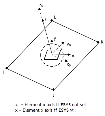
The element geometry, node locations, connectivity, and the nodal coordinate system are shown in Figure 195.1: INTER195 Geometry. The element geometry is defined by 8 nodes, which form bottom and top surfaces of the element. The bottom surface is defined by nodes, I, J, K, L; and the top surface is defined by nodes, M, N, O, P. As shown, the element connectivity is defined as I, J, K, L, M, N, O, P.
Temperatures may be input as element body loads at the nodes. The node I temperature T(I), defaults to TUNIF. If all other temperatures are unspecified, they default to T(I). For any other input pattern, unspecified temperatures default to TUNIF.
By default, the element is capable of both through-thickness and transverse shear deformations (KEYOPT(2) = 1). The inclusion of transverse shear stiffness is generally required when the interfaces between the gasket and the mating parts are modeled as sliding contact. However, if the interfaces are modeled with a matching mesh method (that is, with coincident nodes), ANSYS, Inc. recommends using through-thickness deformation only (KEYOPT(2) = 0) to avoid unnecessary in-plane interaction between the gasket and the mating parts.
You can define element orientation (ESYS) as described in Coordinate Systems:
The next table summarizes the element input. See Element Input in the Element Reference for a general description of element input.
INTER195 Input Summary
- Nodes
I, J, K, L, M, N, O, P
- Degrees of Freedom
UX, UY, UZ
- Real Constants
None
- Material Properties
TB command: Gasket material
MP command: BETD, ALPX (or CTEX or THSX), DMPR
- Body Loads
- Temperatures --
T(I), T(J), T(K), T(L), T(M), T(N), T(O), T(P)
- Special Features
Linear perturbation - KEYOPT(2)
Element deformation:
- 0 --
Through-thickness deformation only
- 1 --
Through-thickness and transverse shear deformation (default)
- KEYOPT(8)
Element component quantity output:
- 0 --
Gasket quantities are output (GKD, GKD, GKI, and GKTH) (default)
- 1 --
Regular stresses and strains are output (including S, EPEL, and EPTH )
INTER195 Output Data
The solution output associated with the element is in two forms:
Nodal items such as nodal displacements are included in the overall nodal solution.
Element items such as stresses and closures are element outputs as shown in Table 195.1: INTER195 Element Output Definitions.
The output directions for element items are parallel to the local element coordinate system based on the element midplane as illustrated in Figure 195.3: INTER195 Stress Output. See Gasket Material in the Mechanical APDL Theory Reference for details.
A general description of solution output is given in Solution Output. See the Basic Analysis Guide for ways to review results.
The Element Output Definitions table uses the following notation:
A colon (:) in the Name column indicates that the item can be accessed by the Component Name method (ESOL). The O column indicates the availability of the items in the file Jobname.OUT. The R column indicates the availability of the items in the results file.
In either the O or R columns, “Y” indicates that the item is always available, a number refers to a table footnote that describes when the item is conditionally available, and “-” indicates that the item is not available.
Table 195.1: INTER195 Element Output Definitions
| Name | Definition | O | R |
|---|---|---|---|
| EL | Element number | - | Y |
| NODES | Node connectivity - I, J, K, L, M, N, O, P | - | Y |
| MAT | Material number | - | Y |
| TEMP | Temperatures T(I), T(J), T(K), T(L), T(M), T(N), T(O), T(P) | - | Y |
| GKS:X, (XY) |
X - Normal stress (also gasket pressure) XY - Transverse shear stress | Y | Y |
| GKD:X, (XY) |
X - Total closure XY - Relative transverse shear deformation ( | Y | Y |
| GKDI:X, (XY, XZ) | Total inelastic closure | Y | Y |
| GKTH:X, (XY, XZ) | Thermal closure | Y | Y |
| S:X, Y, Z, XY | Stresses | - | 1 |
| S:INT | Stress intensity | - | 1 |
| S:EQV | Equivalent stress | - | 1 |
| EPEL:X, Y, Z, XY | Elastic strains | - | 1 |
| EPEL:EQV | Equivalent elastic strain | - | 1 |
| EPTH:X, Y, Z, XY | Thermal strains | - | 1 |
| EPTH:EQV | Equivalent thermal strain | - | 1 |
| SEND:ELASTIC | Strain energy densities | - | 1 |


