Structural
Infinite Solid
INFIN257 Element Description
Use INFIN257 with standard 2-D or 3-D solid elements (the base elements) to model infinite domain in a static analysis.
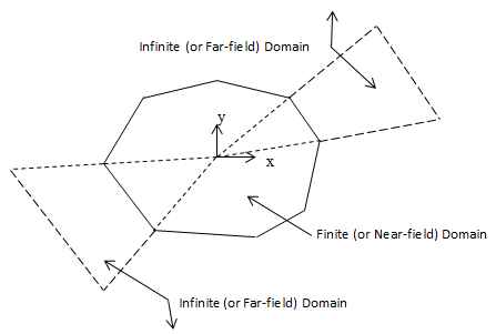
A single layer of elements represents an exterior subdomain of infinite domain; the layer models the effect of far-field decay in structural analyses. Use base elements to model the near-field domain that interacts with the solid structures or applied loads.
For more information about this element, see INFIN257 - Structural Infinite Solid in the Mechanical APDL Theory Reference.
INFIN257 Input Data
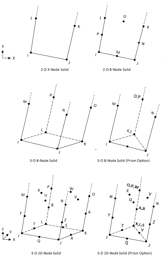
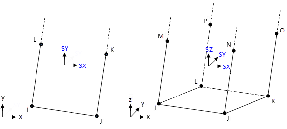
The geometry and nodal locations for this element are shown in Figure 257.2: INFIN257 Geometry.
Create INFIN257 elements from the selected nodes on base elements via the EINFIN command. The command determines the stress state and material properties according to the base element. Only linear elastic material properties (except density) are transferred to INFIN257. The real constant of the thickness input for a 2-D plane stress element (KEYOPT(3) = 3) is copied to the INFIN257 element.
Valid base elements are: PLANE182, PLANE183, SOLID185, SOLID186, SOLID187, and SOLID285.
INFIN257 does not support element loading. Apply element loading to base elements only.
INFIN257 Input Summary
- Nodes
Same as those of the base element, as shown:
Base Element INFIN257 Nodes 2-D 4-Node Solid I, J, K, L 2-D 8-Node Solid I, J, K, L, M, N, O, P 3-D 8 Node Solid I, J, K, L, M, N, O, P 3-D 20-Node Solid I, J, K, L, M, N, O, P, Q, R, S, T, U, V, W, X, Y, Z, A, B 3-D 4-Node Tetrahedral Structural Solid I,J,K,L,M,N,O,P 3-D 10-Node Tetrahedral Structural Solid I,J,K,L,M,N,O,P,Q,R,S,T,U,V,W,X,Y,Z,A,B - Degrees of Freedom
Same as those of the base element, as shown:
Base Element INFIN257 Degrees of Freedom 2-D 4-Node Solid UX, UY 2-D 8-Node Solid 3-D 8-Node Solid UX, UY, UZ 3-D 20-Node Solid 3-D 4-Node Tetrahedral Structural Solid 3-D 10-Node Tetrahedral Structural Solid - Real Constants
None
- Material Properties
None
- Surface Loads
None
- Body Loads
None
- Special Features
None
- KEYOPTS
None
INFIN257 Output Data
The solution output associated with the element is in two forms:
Nodal displacements included in the overall nodal solution
Additional element output as shown in Table 257.1: INFIN257 Element Output Definitions
A general description of solution output is given in Solution Output. See the Basic Analysis Guide for ways to view results.
Stress directions are in the global directions.
The Element Output Definitions table uses the following notation:
A colon (:) in the Name column indicates that the item can be accessed by the Component Name method (ETABLE, ESOL). The O column indicates the availability of the items in the file Jobname.OUT. The R column indicates the availability of the items in the results file.
In either the O or R columns, “Y” indicates that the item is always available, a number refers to a table footnote that describes when the item is conditionally available, and “-” indicates that the item is not available.
Table 257.1: INFIN257 Element Output Definitions
| Name | Definition | O | R |
|---|---|---|---|
| EL | Element Number | - | Y |
| NODES | Nodes - I, J, K, L (2-D) Nodes - I, J, K, L, M, N, O, P (3-D) | - | Y |
| MAT | Material number | - | Y |
| XC, YC, ZC | Location where results are reported. | Y | 1 |
| S:X, Y, Z, XY, YZ, XZ | Stresses (SZ = 0.0 for plane stress elements) | Y | Y |
| S:1, 2, 3 | Principal stresses | - | Y |
| EPEL:X, Y, Z, XY, YZ, XZ | Elastic strains | Y | Y |
| LOCI:X, Y, Z | Integration point locations | - | 2 |
For axisymmetric solutions in the global coordinate system, the X, Y, Z, and XY stress and strain outputs correspond to the radial, axial, hoop, and in-plane shear stresses and strains, respectively.
Table 257.2: INFIN257 Item and Sequence Numbers lists output available (ETABLE) using the Sequence Number method. The table is applied only if the base element is 2-D and KEYOPT(3) = 3. See Creating an Element Table in the Basic Analysis Guide and The Item and Sequence Number Table in this reference for more information. The following notation is used in the table:
- Name
Output quantity as defined in Table 257.1: INFIN257 Element Output Definitions
- Item
Predetermined
Itemlabel for the ETABLE command- E
Sequence number for single-valued or constant element data
- I, J, K, L
Sequence number for data at nodes I, J, K, and L
INFIN257 Assumptions and Restrictions
The element supports static, transient, and harmonic analyses.
In a transient or harmonic analysis, traction at the interface from a static load step is not transferred to the absorbing boundary.
A valid base element must be present for each INFIN257 element.
Valid base element types are: PLANE182, PLANE183, SOLID185, SOLID186, SOLID187, and SOLID285.
Because the element has no pressure degree of freedom, using it with pressure degree-of-freedom (DOF) base elements may give poor results in the finite domain.
In a static analysis, base elements can have anisotropic material properties. It is good practice, however, to limit the finite element domain to a reasonable size so that INFIN257 elements are in a linear elastic state.
Layered solid elements (an option available with SOLID185 and SOLID186, for example) are not compatible with INFIN257 elements.
The element technology of a base element is not transferred to infinite elements.
For 2-D models, the element must lie in a global XY plane as shown in Figure 257.2: INFIN257 Geometry, and the Y axis must be the axis of symmetry for axisymmetric analyses. Model an axisymmetric infinite element in the same quadrants in which the base element is modeled.
For 2-D INFIN257 elements, degeneration is not allowed and generalized plain strain is not supported.
3-D INFIN257 elements must have 8 or 20 nodes. You can form a prism-shaped element by using a degenerated base element.