The following topics related to acoustic output properties are available:
Either the total nodal pressure or the scattered nodal pressure is solved and output at the nodes. Using the calculated nodal pressure values, the pressure gradient is evaluated at the nodes and the element centroid, which is expressed as follows:
 | (8–167) |
Both the nodal velocity (output as PG on the PRNSOL, PLNSOL, and NSOL commands) and the element centroid velocity (output as SMISC on the element table) are calculated for modal (ANTYPE,MODAL) and full harmonic (ANTYPE,HARM) analyses as follows:
 | (8–168) |
The nodal and element centroid sound pressure levels (SPL) are output in the post-processor. SPL is given by:
 | (8–169) |
where:
 (input as PREF on the R command, defaults to 20 x 10-6Pa) (input as PREF on the R command, defaults to 20 x 10-6Pa) |

|
In the frequency domain, the time-average root mean square
quantities are calculated over one period of the sinusoidal function. In the time domain,
the time-average root mean square quantities are calculated over the time increment
 .
.
The A-weighted sound pressure level (dBA) in the frequency domain is defined by:
 | (8–170) |
where:

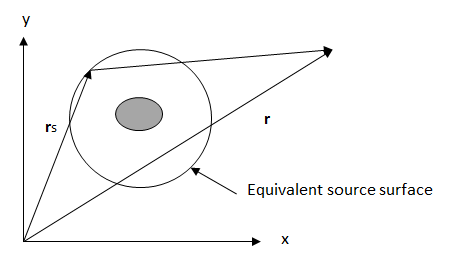
The far-field pressure parameters (output via the PLFAR and PRFAR command) outside of the model are expressed as:
 | (8–171) |
where:
 = enclosed equivalent source surface (defined as
MXWF on SF command) = enclosed equivalent source surface (defined as
MXWF on SF command) |
 = Green's function in radiation space (defaults to free space) = Green's function in radiation space (defaults to free space) |
 | (8–172) |
 = far-field observation position = far-field observation position |
 = equivalent source position
on the enclosed surface = equivalent source position
on the enclosed surface |
| k = wave number (k is equal to zero for an incompressible fluid) |
The Rayleigh integral predicts the radiated far-field pressure from a vibrating panel with an infinite baffle:
 | (8–173) |
where:
 = fluid density = fluid density |
 = angular velocity = angular velocity |
 = normal displacement = normal displacement |
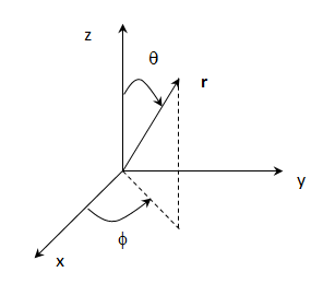
All acoustic far-field parameters are evaluated in the global spherical coordinate system shown in the following figure:
The sound power level radiated by the sound source is expressed as:
 | (8–174) |
where:
| Wref = reference sound power (defaults to 10-12 w) |
| Wrad = radiated sound power |
The radiated sound power is expressed as:
 | (8–175) |
The directivity of the sound source is expressed as:
 | (8–176) |
where:
 |
 |
 |
The directivity of the sound source is also expressed as:
 | (8–177) |
The target strength (TS) is used to describe the reflected acoustic signals. Target strength is given by:
 | (8–178) |
where:
| R = radius at the target position |
| psc = scattered pressure at the target position |
The time-averaged sound power through an area S in a harmonic analysis is defined by:
 | (8–179) |
where:
| p = complex pressure |
| v* = complex conjugate velocity |
In a network, the return loss and transmission loss are respectively defined as:
 | (8–180) |
 | (8–181) |
where:
| Pin = incident sound power at inlet |
| Pr = reflected sound power at inlet |
| Pt = transmitted sound power at outlet |
The sound power parameters are output via the PRFAR, PLFAR, PRAS or PLAS command.
The acoustic surface quantities on the selected surface are defined as follows (and are output via the PRAS and PLAS commands):
Specified acoustic impedance:

Acoustic impedance:

Mechanical impedance:

where:
 = pressure on the surface = pressure on the surface |
 = normal component of velocity on the surface = normal component of velocity on the surface |
 = surface area = surface area |
The acoustic volumetric quantities on the selected elements are defined as follows (output by the PRAS and PLAS commands).
Acoustic time-averages potential energy:
 | (8–182) |
Acoustic time-averaged kinetic energy:
 | (8–183) |
Average square of the L2 norm of pressure:
 | (8–184) |
where:
 = root mean square of acoustic
pressure = root mean square of acoustic
pressure |
 = speed of sound = speed of sound |
 = mass density = mass density |
 = root mean square of particle
velocity = root mean square of particle
velocity |
If the frequency range  is equally divided into
  segments and the pressures are calculated at the center of the frequency
segment
segments and the pressures are calculated at the center of the frequency
segment  , the sound pressure level (SPL) of the frequency range is defined as
follows (and output via the PRAS and PLAS
commands):
, the sound pressure level (SPL) of the frequency range is defined as
follows (and output via the PRAS and PLAS
commands):
 | (8–185) |
where:
 = SPL of frequency segment = SPL of frequency segment  . . |
The A-weighted SPL of the frequency range  is written
as:
is written
as:
 | (8–186) |

