2-D Structural
Surface Effect
SURF153 Element Description
SURF153 may be used for various load and surface effect applications. It may be overlaid onto a face of any 2-D structural solid element (except axisymmetric harmonic elements PLANE25 and PLANE83). The element is applicable to structural analyses, but for 3-D structural analyses, it must be laid on any global Cartesian Z = constant plane. See SURF153 in the Mechanical APDL Theory Reference for more details about this element.

SURF153 Input Data
The geometry, node locations, and the coordinate system for this element are shown in Figure 153.1: SURF153 Geometry. The element is defined by two or three node points and the material properties. The nodes for this element must share the nodes of the underlying solid element. The element x-axis is along to the I-J line of the element.
The mass and volume calculations use the in-plane element thicknesses at nodes I and J (real constants TKI and TKJ, respectively). Thickness TKI defaults to 0.0, and thickness TKJ defaults to TKI. If KEYOPT(3) = 3, the out-of-plane thickness is input as the real constant TKPS (defaults to 1.0). The mass calculation uses the density (material property DENS, mass per unit volume) and the real constant ADMSUA, the added mass per unit area.
The stress stiffness matrix and load vector calculations use the in-plane force-per-unit length (input as real constant SURT). The elastic foundation stiffness (input as real constant EFS) uses pressure-per-length (or force-per-length-cubed) units. The foundation stiffness can be damped, either by using the material property BETD as a multiplier on the stiffness or by directly using the material property VISC.
See Nodal Loading for a description of element loads. Pressures may be input as surface loads as force-per-length-squared on the element faces as shown by the circled numbers on Figure 153.2: Pressures. SURF153 allows complex pressure loads.
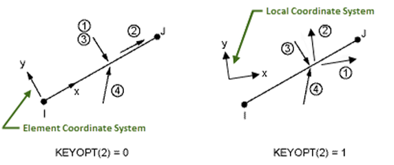
Faces 1 and 2 [KEYOPT(2) = 0] Positive values of pressure on the first two faces act in the positive element coordinate directions (except for the normal pressure which acts in the negative y direction). For face 1, positive or negative values may be removed as requested with KEYOPT(6) to simulate the discontinuity at the free surface of a contained fluid.
Faces 1 and 2 [KEYOPT(2) = 1] Pressure loads are applied to the element faces according to the local coordinate system as follows: face 1 in the local x direction and face 2 in the local y direction. A local coordinate system must be defined, and the element must be set to that coordinate system via the ESYS command; however, the loads specified in that local coordinate system do not follow the large displacements and/or rotations of the element. KEYOPT(6) does not apply.
Face 3 The magnitude of the pressure at each integration
point is PI + XPJ +
YPK, where PI through
PK are input as VAL1 through VAL3 on the SFE command, and X and Y are the global Cartesian coordinates at the
current location of the point. No input values can be blank. The SFFUN and SFGRAD commands do not work
with face 3.
Face 4 The magnitude of the pressure is PI, and the direction is  where i and j are unit vectors in the global Cartesian directions.
The load magnitude can be adjusted with KEYOPTs(11) and (12). No
input values can be blank. When using the SFFUN or SFGRAD commands, the load direction is not
altered, but the load magnitude is the average of the computed corner
node magnitudes. SFCUM,ADD should be used with
caution, as this command also causes the load direction components
to be added.
where i and j are unit vectors in the global Cartesian directions.
The load magnitude can be adjusted with KEYOPTs(11) and (12). No
input values can be blank. When using the SFFUN or SFGRAD commands, the load direction is not
altered, but the load magnitude is the average of the computed corner
node magnitudes. SFCUM,ADD should be used with
caution, as this command also causes the load direction components
to be added.
The effects of pressure load stiffness are automatically included for this element for real pressure on face 1 if KEYOPT(2) = 0 or on face 3. If an unsymmetric matrix is needed for pressure load stiffness effects, use NROPT,UNSYM.
Temperatures may be input as element body loads at the nodes. Element body load temperatures are not applied to other elements connected at the same nodes. The node I temperature T(I) defaults to TUNIF. The node J temperature defaults to T(I). Temperatures are used for material property evaluation only.
When KEYOPT(4) = 0, a removed midside node implies that the displacement varies linearly, rather than parabolically. See Quadratic Elements (Midside Nodes) in the Modeling and Meshing Guide for more information about the use of midside nodes.
If a single PLANE element lies beneath SURF153, you can automatically set the element behavior (plane stress, axisymmetric, or plane stress with thickness [including TKPS if applicable]) to that of the underlying solid element using KEYOPT(3) =10. This option is valid only when a single PLANE element lies beneath the SURF element. For example, if you apply a SURF153 element over a PLANE77 (thermal) element whose nodes are also used in the definition of a PLANE183 (structural) element, a warning appears and the load is not applied to the element.
KEYOPT(7) = 1 is useful when the element is used to represent a force. When KEYOPT(7) = 0, the force is input as a pressure times an area; however, if the area changes due to large deflections, the force also changes. When KEYOPT(7) = 1, the force remains unchanged even if the area changes.
A summary of the element input is given in "SURF153 Input Summary". A general description of element input is given in Element Input. For axisymmetric applications see Harmonic Axisymmetric Elements.
SURF153 Input Summary
- Nodes
I, J if KEYOPT (4) = 1, I, J, K if KEYOPT(4) = 0 - Degrees of Freedom
UX, UY
- Real Constants
(Blank), (Blank), (Blank), EFS, SURT, ADMSUA, TKI, TKJ, (Blank), (Blank), (Blank), TKPS See Table 153.1: SURF153 Real Constants for a description of the real constants - Material Properties
MP command: DENS, VISC, ALPD, BETD, DMPR
- Surface Loads
- Pressures --
face 1 (I-J) (in -y normal direction if KEYOPT(2) = 0; in local coordinate x direction if KEYOPT(2) = 1) face 2 (I-J) (in +x tangential direction if KEYOPT(2) = 0; in local coordinate y direction if KEYOPT(2) = 1) face 3 (I-J) (in -y normal direction, global taper) face 4 (I-J) (oriented by input vector)
- Body Loads
- Temperatures --
T(I), T(J); also T(K) if KEYOPT(4) = 0
- Special Features
Birth and death Large deflection Linear perturbation Nonlinear adaptivity Rezoning Stress stiffening - KEYOPT(2)
Pressure applied to faces 1 and 2 according to coordinate system:
- 0 --
Apply face loads in the element coordinate system
- 1 --
Apply face loads in the local coordinate system
- KEYOPT(3)
Element behavior:
- 0 --
Plane stress
- 1 --
Axisymmetric
- 2 --
Plane strain
- 3 --
Plane stress with thickness input (TKPS)
- 5 --
Generalized plane strain
- 10 --
Use the element behavior--plane stress, axisymmetric, plain strain, plane stress with thickness input (including TKPS if applicable), or generalized plane strain--of the underlying solid element.
- KEYOPT(4)
Midside nodes:
- 0 --
Has midside node
- 1 --
No midside node
- KEYOPT(6)
Applicable only to normal direction pressure (faces 1 and 3):
- 0 --
Use pressures as calculated (positive and negative)
- 1 --
Use positive pressures only (negative set to zero)
- 2 --
Use negative pressures only (positive set to zero)
- KEYOPT(7)
Loaded area during large-deflection analyses:
- 0 --
Use new area
- 1 --
Use original area
- KEYOPT(11)
Pressure applied by vector orientation (face 4):
- 0 --
On projected area and includes tangential component
- 1 --
On projected area and does not include tangential component
- 2 --
On full area and includes the tangential component
- KEYOPT(12)
Effect of the direction of the element normal (element y-axis) on vector-oriented (face 4) pressure:
- 0 --
Pressure load is applied regardless of the element normal orientation
- 1 --
Pressure load is not used if the element normal is oriented in the same general direction as the pressure vector
Table 153.1: SURF153 Real Constants
| No. | Name | Description |
|---|---|---|
| 1 ... 3 | (Blank) | -- |
| 4 | EFS | Foundation stiffness |
| 5 | SURT | Surface tension |
| 6 | ADMSUA | Added mass/unit area |
| 7 | TKI | In-plane thickness at node I |
| 8 | TKJ | In-plane thickness at node J (defaults to TKI) |
| 9 ... 11 | (Blank) | -- |
| 12 | TKPS | Out-of-plane thickness if KEYOPT(3) = 3 (defaults to 1.0) |
SURF153 Output Data
The solution output associated with the element is in two forms:
Nodal degree of freedom results included in the overall nodal solution
Additional element output as shown in Table 153.2: SURF153 Element Output Definitions
A general description of solution output is given in Solution Output. See the Basic Analysis Guide for ways to view results.
The Element Output Definitions table uses the following notation:
A colon (:) in the Name column indicates that the item can be accessed by the Component Name method (ETABLE, ESOL). The O column indicates the availability of the items in the file Jobname.OUT. The R column indicates the availability of the items in the results file.
In either the O or R columns, “Y” indicates that the item is always available, a number refers to a table footnote that describes when the item is conditionally available, and “-” indicates that the item is not available.
Table 153.2: SURF153 Element Output Definitions
| Name | Definition | O | R |
|---|---|---|---|
| EL | Element Number | Y | Y |
| SURFACE NODES | Nodes - I, J | Y | Y |
| EXTRA NODE | Extra node (if present) | Y | Y |
| MAT | Material number | Y | Y |
| AREA | Surface area | Y | Y |
| VOLU: | Volume | Y | Y |
| XC, YC | Location where results are reported | Y | 6 |
| VN(X, Y) | Components of unit vector normal to center of element | - | Y |
| PRESSURES(F/L2) | Pressures P1, P2, P3, P4 at nodes I, J (Face indicated by PRES LOAD KEY) | 1 | - |
| PY, PX | Pressures at nodes in element coordinate system (P4 uses an average element coordinate system) | - | 1 |
| AVG. FACE PRESSURE | Average normal pressure (P1AVG), Average tangential pressure (P2AVG), Average tapered normal pressure (P3AVG), Effective value of vector oriented pressure (P4EFF) | 1 | 1 |
| DVX, DVY | Direction vector of pressure P4 | 1 | 1 |
| TEMP | Surface temperatures T(I), T(J), T(K) | 2 | 2 |
| DENSITY | Density (input as DENS) | 3 | 3 |
| MASS | Mass of Element | 3 | 3 |
| FOUNDATION STIFFNESS | Foundation Stiffness (input as EFS) | 4 | 4 |
| FOUNDATION PRESSURE | Foundation Pressure | 4 | 4 |
| SURFACE TENSION | Surface Tension (input as SURT) | 5 | 5 |
Available only at centroid as a *GET item.
Table 153.3: SURF153 Item and Sequence Numbers lists output available through the ETABLE command using the Sequence Number method. See The General Postprocessor (POST1) in the Basic Analysis Guide and The Item and Sequence Number Table in this reference for more information. The following notation is used in Table 153.3: SURF153 Item and Sequence Numbers:
- Name
output quantity as defined in the Table 153.2: SURF153 Element Output Definitions
- Item
predetermined Item label for ETABLE command
- E
sequence number for single-valued or constant element data
- I,J
sequence number for data at nodes I and J
Table 153.3: SURF153 Item and Sequence Numbers
| Output Quantity Name | ETABLE and ESOL Command Input | |||
|---|---|---|---|---|
| Item | E | I | J | |
| PY (real) | SMISC | - | 1 | 2 |
| PX (real) | SMISC | - | 3 | 4 |
| PY (imaginary) | SMISC | 27 | 28 | |
| PX (imaginary) | SMISC | 29 | 30 | |
| P1AVG (real) | SMISC | 13 | - | - |
| P2AVG (real) | SMISC | 14 | - | - |
| P3AVG (real) | SMISC | 15 | - | - |
| P4EFF (real) | SMISC | 16 | - | - |
| P1AVG (imaginary) | SMISC | 39 | - | - |
| P2AVG (imaginary) | SMISC | 40 | - | - |
| P3AVG (imaginary) | SMISC | 41 | - | - |
| P4EFF (imaginary) | SMISC | 42 | - | - |
| FOUNDATION PRESSURE | SMISC | 21 | - | - |
| AREA | NMISC | 1 | - | - |
| VNX | NMISC | 2 | - | - |
| VNY | NMISC | 3 | - | - |
| EFS | NMISC | 5 | - | - |
| SURT | NMISC | 6 | - | - |
| DENS | NMISC | 7 | - | - |
| MASS | NMISC | 8 | - | - |
| DVX | NMISC | 9 | - | - |
| DVY | NMISC | 10 | - | - |
SURF153 Assumptions and Restrictions
The element must not have a zero length.
The surface tension load vector acts along the line connecting nodes I and J as a force applied to the nodes seeking to minimize the length of the line. If the nodes of the element are not coplanar when using surface tension, equilibrium may be lost.
For structural large deflection analyses, the loads are applied to the current size of the element, not the initial size.
Surface printout and foundation stiffness are not valid for elements deactivated [EKILL] and then reactivated [EALIVE]. Surface printout does not include large strain effects.
For rezoning, only normal and tangential pressures applied on SURF153 are supported. (That is, rezoning support is available only for pressure on faces 1 and 2.)
SURF153 Product Restrictions
When used in the product(s) listed below, the stated product-specific restrictions apply to this element in addition to the general assumptions and restrictions given in the previous section.
ANSYS Mechanical Pro
Birth and death is not available.
Linear perturbation is not available.
Rezoning is not available.
ANSYS Mechanical Premium
Birth and death is not available.
Rezoning is not available.