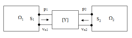
A complicated structure may be trimmed and represented by a 2×2 transfer admittance matrix that is a part of the finite element model.
The transfer admittance matrix is given by:
 | (8–188) |
where:
| p1 = pressure at port 1 |
| vn1 = normal velocity at port 1 |
| p2 = pressure at port 2 |
| vn2 = normal velocity at port 2 |
| Y11, Y22 = self-admittances |
| Y12, Y21 = mutual admittances |
| α1, α2 = internal sources (usually equal to zero in an acoustic analysis) |
The following related topics are available:
When two acoustic domains are separated by a transfer admittance matrix, the boundary surface integrations with the normal velocity on the S1 and S2 surfaces in the “weak” form (Equation 8–8-Equation 8–10) are given by:
 | (8–189) |
 | (8–190) |
where:
| [C] = damping matrix |
The outward normal vectors o the integration surface point toward the inside of the transfer admittance matrix. It is consistent with the defined direction of normal velocity in the transfer admittance matrix. Therefore, the velocity vector can be replaced by the pressure via the transfer admittance matrix, while the ports of the transfer admittance matrix are connected to the surface S1 and S2 such that:
 | (8–191) |
The equivalent damping and stiffness matrices are given by:
 | (8–192) |
 | (8–193) |
where the indices r and I represent the real and imaginary part of a complex variable.
The internal source is cast by:
 | (8–194) |
Assume the transfer admittance matrix to represent porous material on a structural surface, i.e. a port of the transfer admittance matrix is connected to the FSI interface.
The “weak” form in the structural domain is given by:
 | (8–195) |
The “weak” form in the acoustic domain is given by:
 | (8–196) |
where:
| n F,1 is the outward normal unit vector of the porous material domain and points toward the solid |
| n F,2 is the outward normal unit vector of the acoustic domain and points toward the porous material |
In the fluid domain

The transfer admittance matrix (Equation 8–188) is also written as:
 | (8–197) |
where:
| n S,1 = the outward normal unit vector of the structural domain |
| ps = the pressure on the surface S1 of the structural domain |
| v s = the particle velocity on the surface S1 of the structural domain |
| pa = the pressure on the surface S2 of the acoustic domain |
| v a = the particle velocity on the surface S2 of the acoustic domain |
The transformation of the transfer admittance matrix in Equation 8–197 is given by:
 | (8–198) |
where:

With  and
and  , the transformed transfer admittance matrix is re-written
as:
, the transformed transfer admittance matrix is re-written
as:
 | (8–199) |
Considering the continuous boundary condition on the FSI interface:
 | (8–200) |
The boundary integration in the structure “weak” form is given by:
 | (8–201) |
Using Equation 8–8 and Equation 8–9, the boundary integration in the acoustic “weak” form is given by:

Substituting the boundary integrations into Equation 8–195 and Equation 8–196, the coupled matrix equation is derived as:
 | (8–202) |
where:


It is impossible to evaluate (Nn} on the acoustic surface S2, since the normal vector n F,1 is involved. An alternative is to evaluate {Nn} on the solid surface S1, for instance:
