This section contains shape functions for 3-D solid elements. These elements are available in a number of configurations, including certain combinations of the following features:
Element shapes may be tetrahedra, pyramids, wedges, or bricks (hexahedra).
- If wedges or bricks, with or without extra shape functions (ESF)
With or without rotational degrees of freedom (RDOF)
With or without midside nodes
The wedge elements with midside nodes (15-node wedges) are either a condensation of the 20-node brick element or are based on wedge shape functions.
These shape functions are either a direct 4-node tetrahedral such as SOLID285 or a condensation of an 8-node brick element such as SOLID5, FLUID30, or SOLID98.
The resulting effective shape functions are:
(11–172) |
(11–173) |
(11–174) |
(11–175) |
(11–176) |
(11–177) |
(11–178) |
(11–179) |
(11–180) |
(11–181) |
(11–182) |
(11–183) |
These shape functions are for 10-node tetrahedron elements such as SOLID98 and SOLID227, or by condensation for SOLID90.
(11–184) |
(11–185) |
(11–186) |
(11–187) |
(11–188) |
(11–189) |
(11–190) |
This element is a condensation of an 8-node brick element.
The resulting effective shape functions are:
(11–191) |
These shape functions are for 13-node pyramid elements which are based on a condensation of a 20-node brick element:
(11–192) |
(11–193) |
(11–194) |
(11–195) |
(11–196) |
(11–197) |
The 6-node wedge elements are a condensation of an 8-node brick such as SOLID5 or FLUID30. These shape functions are for 6-node wedge elements without extra shape functions:
(11–198) |
(11–199) |
(11–200) |
(11–201) |
(11–202) |
(11–203) |
(11–204) |
The 6-node wedge elements are a condensation of an 8-node brick such as SOLID5. (See Figure 11.14: 6-Node Wedge Element.) These shape functions are for 6-node wedge elements with extra shape functions:
(11–205) |
(11–206) |
(11–207) |
These shape functions are for 15-node wedge elements such as SOLID90 that are based on a condensation of a 20-node brick element Equation 11–232. or are computed directly.
Elements in a wedge configuration use shape functions based on triangular coordinates and the r coordinate going from -1.0 to +1.0.
(11–208) |
(11–209) |
(11–210) |
(11–211) |
(11–212) |
(11–213) |
These shape functions are for 8-node brick elements without extra shape functions such as SOLID5 with KEYOPT(3) = 1 or FLUID30:
(11–214) |
(11–215) |
(11–216) |
(11–217) |
(11–218) |
(11–219) |
(11–220) |
(11–221) |
(11–222) |
(11–223) |
(11–224) |
(11–225) |
(11–226) |
(11–227) |
(11–228) |
(Please see Figure 11.16: 8-Node Brick Element) These shape functions are for 8-node brick elements with extra shape functions such as SOLID5 with KEYOPT(3) = 0:
(11–229) |
(11–230) |
(11–231) |
These shape functions are used for 20-node solid elements such as SOLID90:
(11–232) |
(11–233) |
(11–234) |
(11–235) |
(11–236) |
(11–237) |
(11–238) |
These shape functions and mapping functions are for the 3-D 8-node solid brick infinite elements such as INFIN111:
These shape functions and mapping functions are for the 3-D 20-node solid brick infinite elements such as INFIN111:
This section contains shape functions for general axisymmetric solid elements. These elements are available in a number of configurations, including certain combinations of the following features:
A quadrilateral, or a degenerated triangle shape to simulate an irregular area, on the master plane (the plane on which the quadrilaterals or triangles are defined)
With or without midside nodes
A varying number of node planes (Nnp) in the circumferential direction (defined via KEYOPT(2))
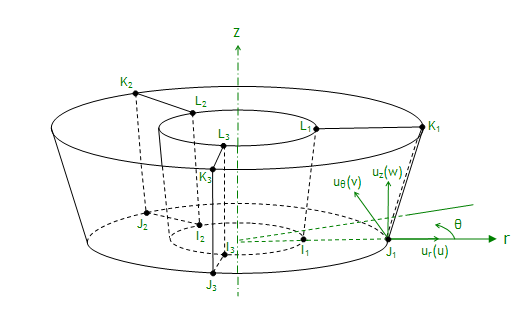
The elemental coordinates are cylindrical coordinates and displacements are defined and interpolated in that coordinate system, as shown in Figure 11.20: General Axisymmetric Solid Elements (when Nnp = 3).
When Nnp is an odd number, the interpolation function used for displacement is:
(11–263) |
where:
| i = r, θ, z |
| hi (s, t) = regular Lagrangian polynominal interpolation functions like Equation 11–120 or Equation 11–134. |
|
|
When Nnp is an even number, the interpolation function is:
(11–264) |
The temperatures are interpolated by Lagrangian polynominal interpolations in s, t plane, and linearly interpolated with θ in circumferential (θ) direction as:
(11–265) |
where:
|
|
|
|
| Tn = same as Equation 11–128 and Equation 11–138. |
All of the coefficients in Equation 11–263 and Equation 11–264 can be expressed by node displacements. Using ur = u, uj = v, uz = w, and take Nnp = 3 as an example.
(11–266) |
(11–267) |
(11–268) |
