
| Matrix or Vector | Option | Shape Functions | Integration Points |
|---|---|---|---|
| Stiffness and Stress Stiffness Matrices; and Thermal and Newton-Raphson Load Vectors | Linear (KEYOPT(3)=0) | Equation 11–6, Equation 11–7, Equation 11–8, Equation 11–9, Equation 11–10, and Equation 11–11 |
Along the length: 1 Across the section: see text below |
| Quadratic (KEYOPT(3)=2) | Equation 11–19, Equation 11–20, Equation 11–21, Equation 11–22, Equation 11–23, and Equation 11–24 |
Along the length: 2 Across the section: see text below | |
| Cubic (KEYOPT(3)=3) | Equation 11–26, Equation 11–27, Equation 11–28, Equation 11–29, Equation 11–30, and Equation 11–31 |
Along the length: 3 Across the section: see text below | |
| Consistent Mass Matrix and Pressure, Hydrostatic, and Hydrodynamic Load Vectors | Linear (KEYOPT(3)=0) | Equation 11–6, Equation 11–7, Equation 11–8, Equation 11–9, Equation 11–10, and Equation 11–11 |
Along the length: 2 Across the section: 1 |
| Quadratic (KEYOPT(3)=2) | Equation 11–19, Equation 11–20, Equation 11–21, Equation 11–22, Equation 11–23, and Equation 11–24 |
Along the length : 3 Across the section: 1 | |
| Cubic (KEYOPT(3)=3) | Equation 11–26, Equation 11–27, Equation 11–28, Equation 11–29, Equation 11–30, and Equation 11–31 |
Along the length: 4 Across the section: 1 | |
| Lumped Mass Matrix | Linear (KEYOPT(3) = 0) | Equation 11–6, Equation 11–7, and Equation 11–8 |
Along the length: 2 [1 Across the section: 1 |
| Quadratic (KEYOPT(3) = 2) | Equation 11–19, Equation 11–20, and Equation 11–21 |
Along the length : 3 [1] Across the section: 1 | |
| Cubic (KEYOPT(3) = 3) | Equation 11–26, Equation 11–27, and Equation 11–28` |
Along the length: 4 [1] Across the section: 1 |
| Load Type | Distribution |
|---|---|
| Element Temperature |
KEYOPT(1) = 0 Linear through wall and linear along length KEYOPT(1) = 1 Bilinear across cross-section and linear along length |
| Nodal Temperature | Constant across cross-section, linear along length |
| Internal and External Pressures | Constant, except as adjusted by the affect of internal and external fluids. |
References: Simo and Vu-Quoc([238]), Ibrahimbegovic([239]).
The element is based on Timoshenko beam theory; therefore, shear deformation effects are included. It uses six components of strain, three direct strains and three shear strains. The element is well-suited for linear, large rotation, and/or large strain nonlinear applications.
The element includes stress stiffness terms, by default, in any analysis using large deformation (NLGEOM,ON). The stress stiffness terms provided enable the elements to analyze flexural, lateral and torsional stability problems (using eigenvalue buckling or collapse studies with arc length methods).
Transverse shear strain is constant through cross-section (that is, cross sections remain plane and undistorted after deformation). The element can be used for slender or stout beams. Due to the limitations of first-order shear deformation theory, slender to moderately thick beams can be analyzed. Slenderness ratio of a beam structure may be used in judging the applicability of the element. It is important to note that this ratio should be calculated using some global distance measures, and not based on individual element dimensions. A slenderness ratio greater than 30 is recommended.
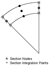
The elements are provided with section relevant quantities (area of integration, position, Poisson function, function derivatives, etc.) automatically at a number of section points by the use of section commands. Each section is assumed to be an assembly of number of nine-node cells. The number of cells in both the circumferential and thickness directions is controlled by the SECDATA command. Each cell has six integration points, as shown in the following figure:
The section includes internal fluid which contributes only mass and applied pressure, and insulation which contributes only mass, and adds to the effective (hydraulic) diameter.
The following ocean effects apply to this element:
The origin for any problem containing PIPE288 using ocean effects must be at the free surface (mean sea level),
although the origin can be offset via the OCDATA command’s Zmsl value. Further,
the Z axis is always the vertical axis, pointing away from the center
of the earth.
If the element is intended to lie on the ocean floor, gap elements must be provided.
The element mass matrix has several components, each organized on a mass-per-unit-length basis:
 | (13–422) |
where:
| ρ = density of the pipe wall (input as DENS on the MP command) |
 | (13–423) |
where:
ρint = density of the internal fluid
(input as DENS on the MP command, with the material
number specified via M
int
on the SECDATA command)
 | (13–424) |
where:
ρi = density of external insulation
(input as DENS on the MP command, with the material
number specified via M
ins
on the SECDATA command) |
 | (13–425) |
where:
mah is input as ADDMAS on the SECCONTROL command |
 | (13–426) |
where:
Ca = coefficient of added mass of the
external fluid (input as Ca on the OCDATA command) |
ρw = fluid density (input as DENS
on the MP command, with the material number specified
via MATOC on the OCDATA command) |
madd only resists submerged lateral acceleration. If the element is above the instantaneous free surface, madd = 0.0 . For modal (ANTYPE,MODAL) and harmonic (ANTYPE,HARMIC) analyses, the surface location does not account for ocean waves.
The element load vector consists of two parts:
Distributed force per unit length to account for hydrostatic (buoyancy) effects ({F/L}b) as well as axial nodal forces due to internal pressure and temperature effects {Fx}.
Distributed force per unit length to account for hydrodynamic effects (current and waves) ({F/L}d).
The hydrostatic and hydrodynamic effects work with the original diameter and length, i.e., initial strain and large deflection effects are not considered.
See Hydrostatic Loads in the Element Tools section of this document.
See Hydrodynamic Loads in the Element Tools section of this document.
Several stress evaluation options exist. The section strains and generalized stresses are evaluated at element integration points and then linearly extrapolated to the nodes of the element.
If the material is elastic, stresses and strains are available after extrapolation in cross-section at the nodes of section mesh. If the material is plastic, stresses and strains are moved without extrapolation to the section nodes (from section integration points).