RSYMM, Option, CS,
Axis, NSECT,
CONDVALUE, SVAL,
EVAL
Defines symmetry, rotation, or extrusion parameters for the
radiosity method.
-
Option Command options:
CLEAR
—
Deletes all symmetry/extrusion definitions. Other command options are ignored.
DEFINE
—
Defines the symmetry/extrusion definition (default).
STAT
—
Shows the status/listing. Other command options are ignored.
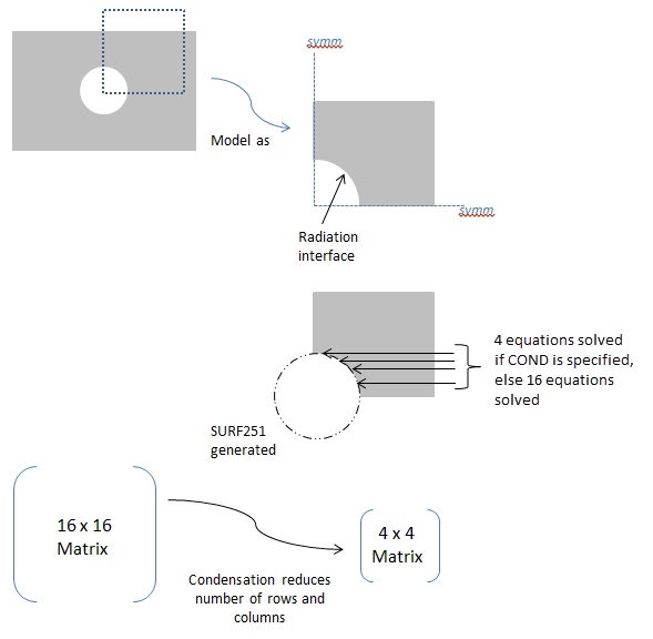
COND
—
Activates or deactivates condensation in the radiosity solver for all defined radiation symmetries/extrusions. Condensation is the process where the radiosity equation system is reduced in size. Default is off. (See Figure 9: Usage Example:
Option= COND .)-
CS Local coordinate system (
 11) as defined using the LOCAL or CS
commands or the global coordinate system (0). For planar reflection, the coordinate system
origin must be on the plane of symmetry (POS) and one of its axes must be normal to the POS.
For cyclic reflection, the coordinate system origin must be coincident with the center of
rotation (COR). Only Cartesian systems are valid.
11) as defined using the LOCAL or CS
commands or the global coordinate system (0). For planar reflection, the coordinate system
origin must be on the plane of symmetry (POS) and one of its axes must be normal to the POS.
For cyclic reflection, the coordinate system origin must be coincident with the center of
rotation (COR). Only Cartesian systems are valid. -
Axis Axis label of the coordinate system (
CS) that is normal to the POS for planar reflection, or label to indicate the type of extrusion. For cyclic reflection, this field must be blank, and it is assumed that the Z axis is aligned with the axis of rotation.X, Y, or Z
—
Planar reflection. For 2-D model planar reflections, valid labels are X or Y. For 3-D model planar reflections, valid labels are X, Y, or Z.
ZEXT
—
Linear extrusion of a line element in the X-Y plane, in the Z direction, to create 4-noded SURF252 elements.
NSECTindicates how many elements will be created.SVALis the starting Z value, andEVALis the ending Z value.CSmust be 0.CEXT
—
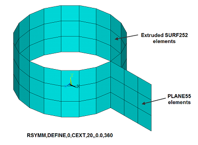
Circumferential extrusion (theta direction) around the global Y-axis. A 2-noded line element in the X-Y plane is extruded to create 4-noded SURF252 elements.
NSECTindicates how many elements will be created.SVALis the starting angle, and EVAL is the ending angle (in degrees). The angles are with respect to the global X-axis.CSmust be 0.(blank)
—
Cyclic reflection.
-
NSECT Number of cyclic reflections to be done, or number of elements in the extrusion direction.
For planar reflection, this field must be 0 or blank.
For cyclic reflection, this field must be ≥ 1 or ≤ -1. Use a positive value if you want the sector angle to be computed automatically. Use a negative value if you want the sector angle to be computed manually. See Notes for details.
-
CONDVALUE Condensation key. Valid only when
Option= COND.ON
—
Activates condensation in the radiosity solver for all defined radiation symmetries/extrusions.
OFF
—
Deactivates condensation in the radiosity solver for all defined radiation symmetries/extrusions (default).
-
SVAL,EVAL Starting and ending Z values (if
Axis= ZEXT) or angle values (ifAxis= CEXT) used for the extrusion. Not used for planar or cyclic reflection.
Notes
The RSYMM command is used to define the plane of symmetry (POS) for planar reflection or the center of rotation (COR) for cyclic reflection. It can also be used to set parameters for a linear or circumferential extrusion. The input provided on this command is used to generate radiosity surface elements (SURF251/SURF252) when the RSURF command is issued.
The RSYMM command must be issued before RSURF, and it may be issued multiple times to have more than one planar/cyclic reflection or extrusion. The RSURF command processes RSYMM commands in the order they are issued.
For planar reflection, you must define a local coordinate system (  11) with its origin on the POS. One of its axes must be aligned so that it is
normal to the plane. If possible, use the existing global coordinate system (0).
11) with its origin on the POS. One of its axes must be aligned so that it is
normal to the plane. If possible, use the existing global coordinate system (0).
For cyclic reflection, you must define a local coordinate system (  11) with its origin coincident with the COR. Reflections occur about the local
Z-axis in the counterclockwise direction. You must align the Z-axis properly. If possible, use
the existing global coordinate system (0).
11) with its origin coincident with the COR. Reflections occur about the local
Z-axis in the counterclockwise direction. You must align the Z-axis properly. If possible, use
the existing global coordinate system (0).
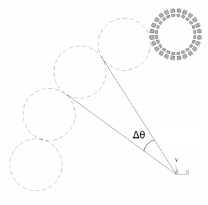
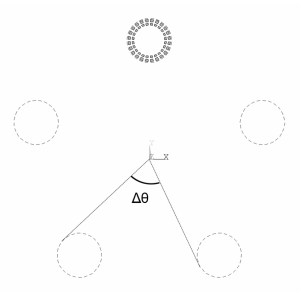
For cyclic reflection, NSECT is used as
follows:


where θmax and θmin are computed internally based on location of the RDSF (surface-to-surface radiation) flagged surfaces.
See Figure 10: Usage Example: Positve and Negative NSECT Values for an example of
NSECT usage.
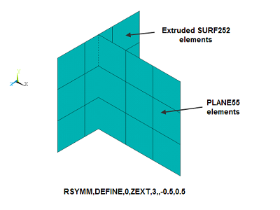
For linear or circumferential extrusion
(Axis = ZEXT or CEXT), you must ensure that the extruded area matches
the area of the underlying element; otherwise, the results may not be correct. For example, in
the case of PLANE55 elements with a planar depth = 10, use
Axis = ZEXT and set SVAL and
EVAL such that EVAL -
SVAL = 10. Likewise, for axisymmetric
PLANE55 elements, use Axis = CEXT and set
SVAL and EVAL such that
EVAL - SVAL = 360. You must also issue
V2DOPT,1 for the axisymmetric case. See Figure 11: Usage Example: Extrusions with Axis = ZEXT and CEXT for
extrusion examples.
The Axis= ZEXT and CEXT options are not
valid for SHELL131 and SHELL132
elements.
New surface elements generated by the RSYMM command inherit the properties of the original elements.
For 2-D axisymmetric models, RSYMM can be used only for symmetrization in the YR plane. It cannot be used for the theta direction. Use V2DOPT in that case.
For 2-D axisymmetric YR models, the newly-generated nodes can have only positive X coordinates.


Distributed ANSYS Restriction This command is not supported in Distributed ANSYS.