SHSD, RID,
Action
Creates or deletes a shell-solid interface to be used in shell-to-solid
assemblies.
RIDThe real constant set ID that identifies the contact pair on which a shell-to-solid assembly is defined. If ALL, all selected contact pairs will be considered for assembly.
ActionCREATE—
Builds new shell and contact elements to be used in shell-to-solid assemblies (default). New elements are stored as internally-created components.
DELETE—
Deletes the nodes and elements created during a previous execution of SHSD,
RID,CREATE for the real constant set identified byRID.
Notes
The SHSD command creates a shell-solid interface to be used in
shell-to-solid assemblies, or deletes a previously-created shell-solid interface.
“Virtual” shell elements and additional CONTA175 elements
are created at the contact pair identified by RID when
Action = CREATE. Set Action = DELETE to
remove the generated nodes and elements at the contact pair identified by
RID.
The SHSD command is active only when the following element KEYOPTs of associated CONTA175 and TARGE170 element types are predefined:
| Element | KEYOPT | Detail |
|---|---|---|
| CONTA175 | KEYOPT(2) = 2 | MPC algorithm |
| KEYOPT(12) = 5, 6 | bonded contact | |
| KEYOPT(4) = 0 | contact normal perpendicular to target surface | |
| TARGE170 | KEYOPT(5) = 1, 2 | types of constraints (1 = translational DOFs only, 2 = translational and rotational DOFs) |
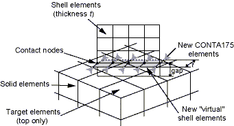
The method used to build shell and contact elements depends on the KEYOPT(5) setting of the
target element type associated with the real constant set identified by the
RID argument. If KEYOPT(5) = 1 (projected constraint with
translational degrees of freedom only), the virtual shell elements are built perpendicular to the
pre-existing shell elements attached to the contact elements. They geometrically follow the
contact interface edge and are built on both sides of this interface in such a way that each new
shell element (SHELL181) has two nodes that belong to the associated
pre-existing shell element in the shell edge. (See Figure 15: Virtual Shell Elements Following the Contact Interface Edge.) The width of
the new shell elements is half the thickness of the pre-existing shell element. The
CONTA175 elements are then created at each node of the virtual shell
elements where no CONTA175 element exists. The new contact elements are
identified by the same contact pair ID as the pre-existing contact elements.
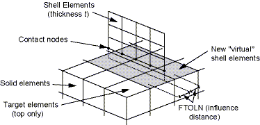
If KEYOPT(5) = 2 (projected constraint with uncoupled translational and rotational degrees
of freedom), the virtual shell elements (SHELL181 - low order;
SHELL281 - high order) overlap the existing high or low order target
elements identified with the RID argument, and share their nodes. Only
those target elements close enough to the contact interface (identified using the PINB real
constant) are overlapped. The program uses the FTOLN real constant (defaults to half the shell
element thickness) to define an influence distance. The associated virtual shell elements are
created only for target elements that lie partially inside the influence distance region (see
Figure 16: Virtual Shell Elements Overlapping Target Elements).
For the bonded always option (KEYOPT(12) = 5), any contact node inside the pinball region (gap < PINB) is included in the KEYOPT(5) = 2 process. A relatively small PINB value may be used to prevent false contact. PINB defaults to 25% of the contact depth for small deformation analyses.
For the bonded initial option (KEYOPT(12) = 6), only those contact nodes which initially lie inside the adjustment zone (gap < ICONT) are always included in the KEYOPT(5) = 2 process. ICONT defaults to 5% of the contact depth.
For both processes, the new nodes and elements are stored in internally-named components.
The internal naming convention is based on the real constant set ID specified by
RID, as illustrated in the following table.
| Nodes | SHSD_ND_RID |
| Contact Elements | SHSD_CN_RID |
| Shell Elements | SHSD_SH_RID |
Issuing SHSD,RID,DELETE deletes components
based on their generated names. Only components whose names match the internal naming
convention will be deleted.
Caution: Do not rename or manually delete generated components. Use the SHSD command to delete generated components.
Renaming or manually deleting generated components will cause these components to be
ignored when SHSD,RID,DELETE is executed and when
ANSYS searches for these components to verify if
SHSD,RID,CREATE can be safely executed. Manually
renaming or deleting generated components and reissuing
SHSD,RID,CREATE may result in erroneous
generation of virtual shell or contact elements.
See Modeling a Shell-Solid Assembly in the Contact Technology Guide for more information.